


|
|
1953
& 1954 Chevrolet Tech-Tips

Enclosed on this
page is some basic technical information on the 1953 and 1954 Chevrolets.
Many of these requests have come from our webpage viewers sending us
requests. Just look at the subject links below and click on the topic
of interest.

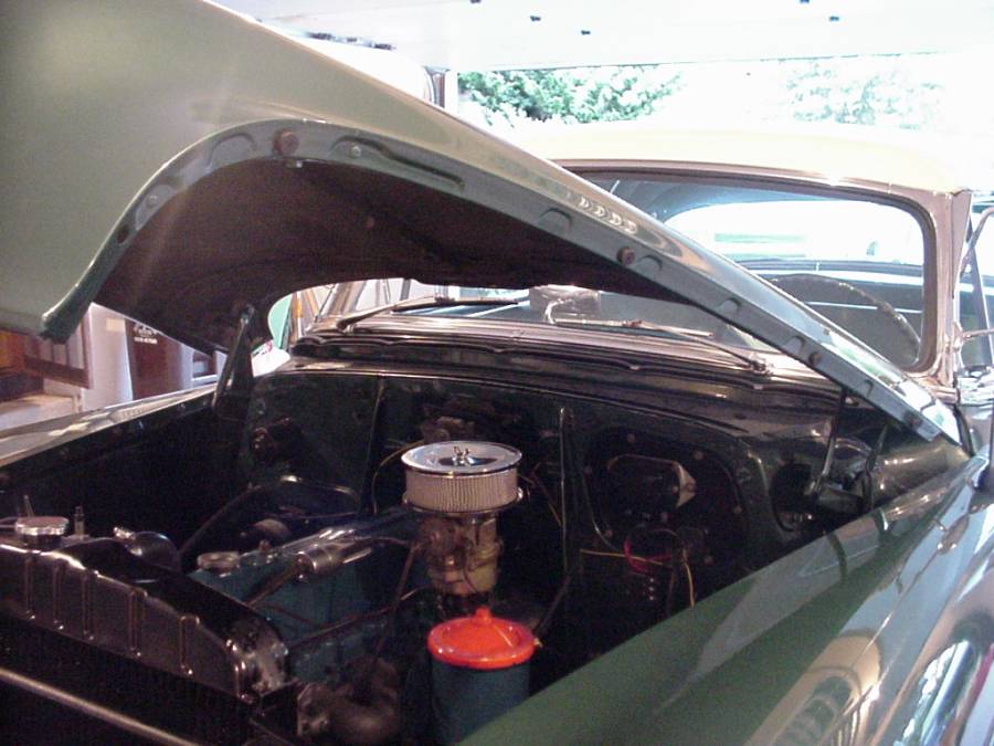
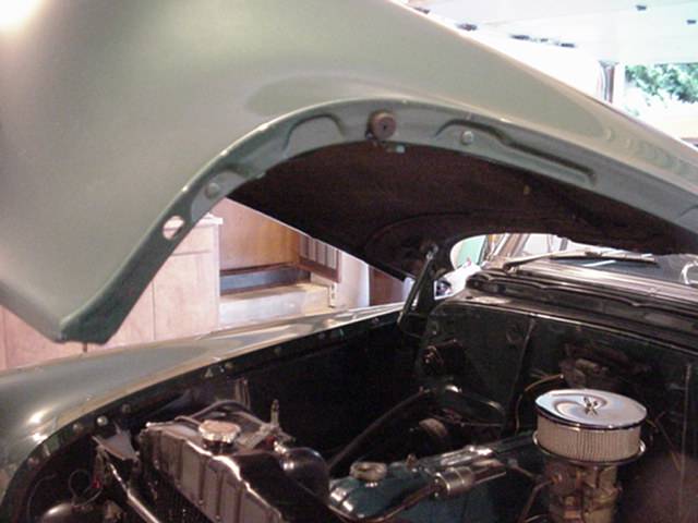
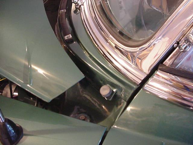
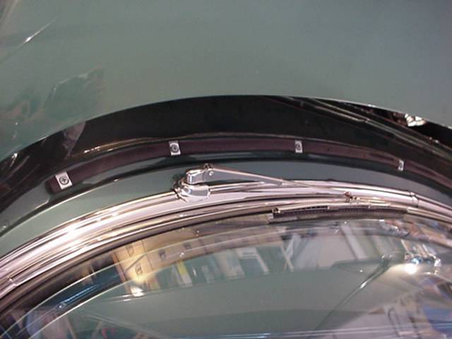
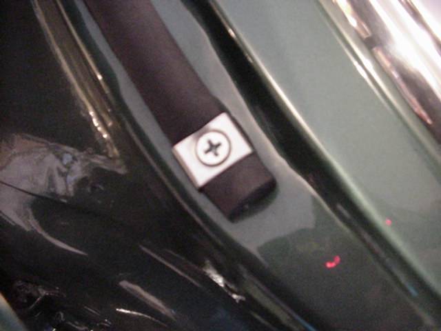
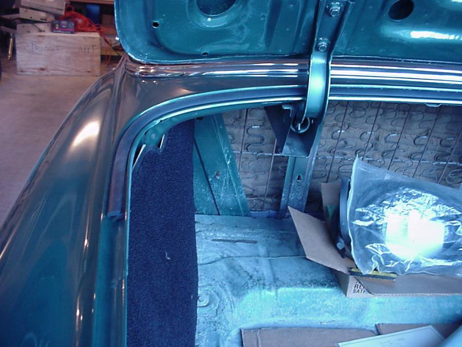
Hood and Trunk Grommet Locations
Location of various hood grommets and trunk weather
sealing. There are 4 grommets on each side of the front hood as shown in the
photos. The trunk has a weather seal that only extends part way down the
metal channel, as noted in the last picture
Horn Problems
I had the most
difficult horn issue that is possible to have on my Bel-Air. One day
the horn started blaring in my parents garage (where the car is stored) and of course I wasn't around.
Luckily my dad disconnected the wires to the horns to shut down the noise. After I checked
out the horn relay and determined that it was fine (checked it with ohmmeter
for continuity), I concluded that the problem was in the horn ring area of
the steering wheel. This was determined by disconnecting the wire that
comes from the horn button (the wire which traverses down the steering column shaft
and connects to a wire that goes through the firewall connecting to the
horn relay) and troubleshooting as follows:
-
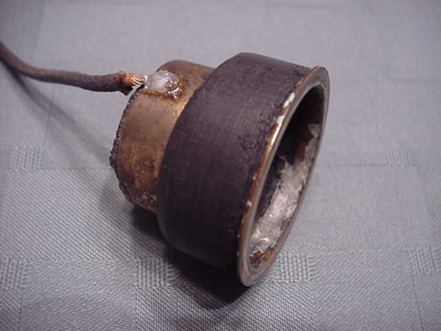
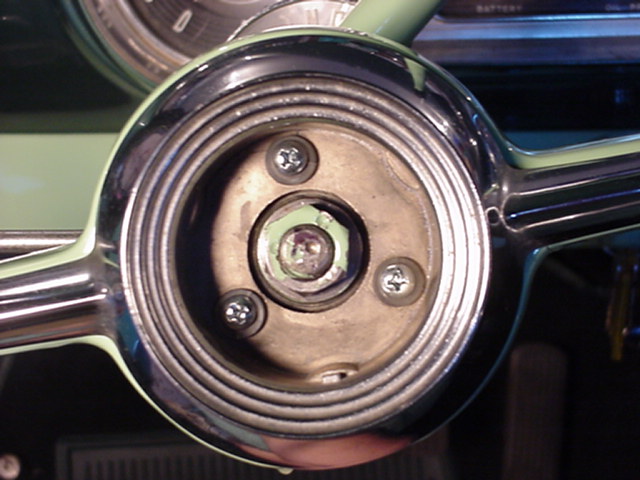
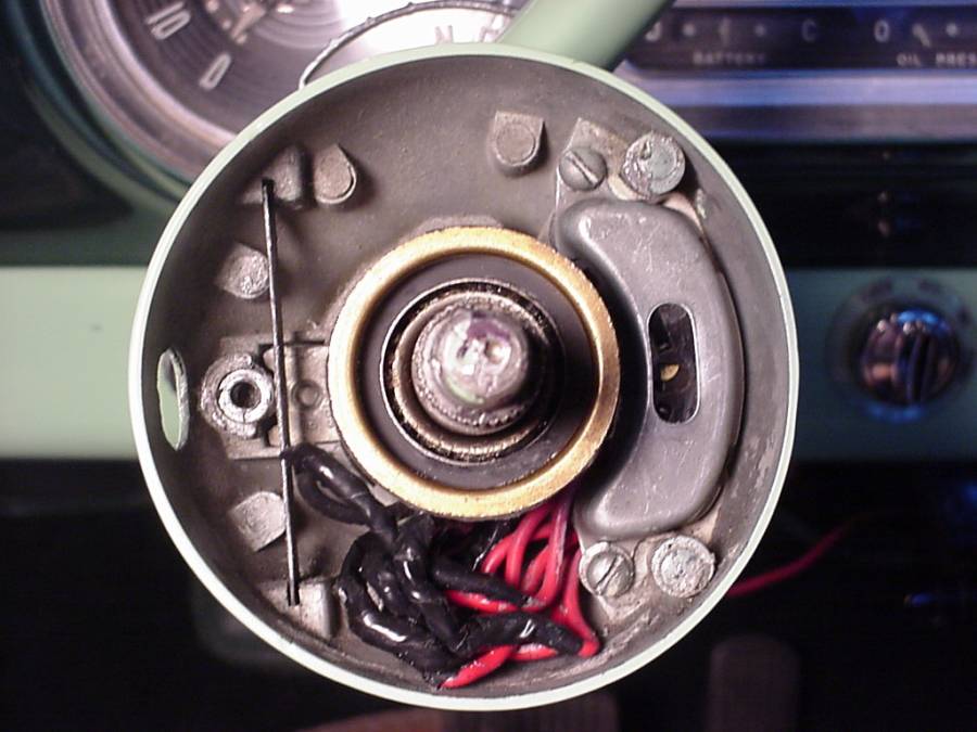
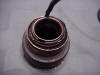
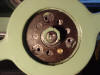
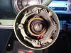
Become familiar with
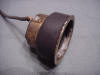
the "Under Steering Wheel Bearing (USWB)" shown in Pictures 1, 2, and 3
below. This is the bad one that I removed from my car. A new one
can be purchased from Chevs of the 40's, part number 270255,
for about $43.
-
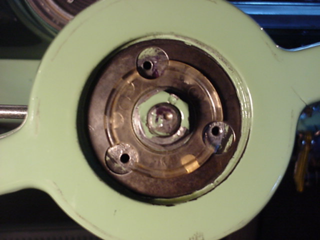
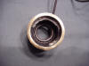
To test and see if
the USWB is bad (with age, the rubber deteriorates and shorts can occur as
picture 2 illustrates), find the wire that comes from the USWB and goes down
the steering wheel shaft and connects to a wire that goes through the
firewall and connects to the horn relay. Disconnect the wires so the
wire coming from the USWB is not connected to anything.
-
Place one lead of
your ohmmeter or continuity checker (+) on the wire that comes form the USWB
(not the wire that goes to the horn relay through the firewall) and the
other lead (-) to chassis ground on the car. This can all be done
without removing the steering wheel...yet.
-
If the ohmmeter
shows zero ohms or low resistance, the problem is either a shorted wire from
the USWB that goes up the
steering shaft column and shorts to ground or a shorted USWB itself (bad
rubber scenario). In
other words, you have a short.
-
If the meter doesn't
move, then, press the horn ring on the steering wheel (honk
your horn). If the meter moves to zero ohms each time you press the horn ring,
then, your problem is not in the steering wheel area or USWB. This
means your horn ring and switch circuitry is ok. You need to go back
and check the horn relay portion of the circuit.
-
The steps below show
how to remove the old USWB and install a new one.
|
|
|
|
1. Under Steering Wheel Bearing USWB
View of old unit removed. |
|
|
|
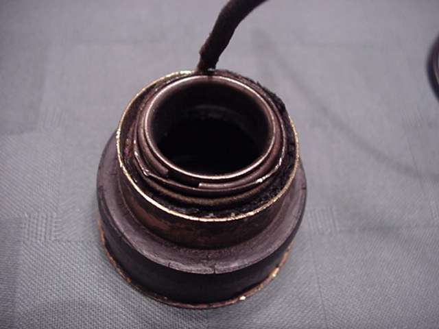
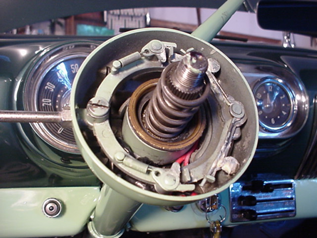
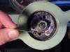
2. Back Side
View of the back. Here is where you can barely see the old rubber dried up between the brass inner and our collar. This causes the short. |
|
|
|
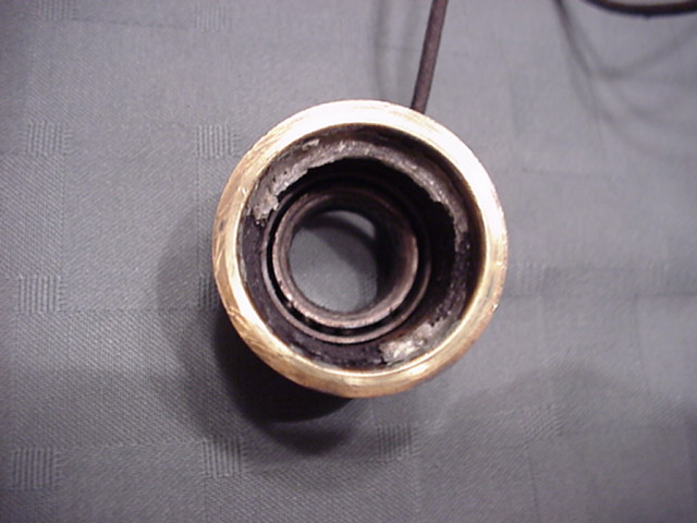
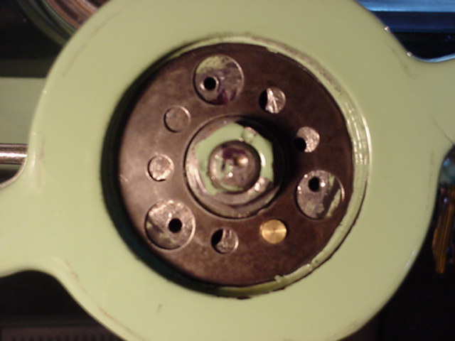
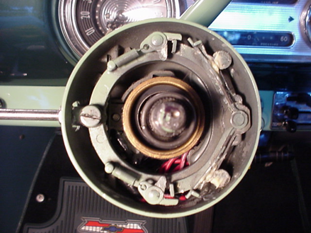
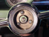
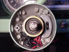
3. Front View
|
|
|
|
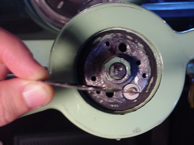
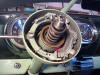
4. Access to Horn Switch Componets - Step A
To get at the turn signal switch and USWB, remove the 3 screws holding the horn ring. Be careful not to loose the plastic insulators. |
|
|
|
5. Access to Horn Switch Componets - Step B
Next, remove the plastic "Horn Pivot Ring". Take careful note, how it lines up with all screw holes. |
|
|
|
|
|
6. Access to Horn Switch Componets - Step C
Remove the "Horn Contact Plate". NOTICE how you remove it. There is a bevel to the metal plate. When laying in the steering wheel, the bevel arches upwards. |
|
|
|
7. Horn Contact Plate
Showing the slight bevel. |
|
|
|
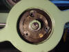
8. Access to USWB
Remove the turn signal switch. Then, slowly pry out the old USWB. Be sure you disconnect the wire from the USWB down below. |
|
|
|
9. New USWB installed
View of new USWB installed. Use a piece of 2x2x12" soft wood against the brass part of the bearing and hit the wood softley to drive the rubber portion of the bearing into the stearing wheel shaft column. |
|
|
|
10. Top View - Completed Installation
Reverse procedure to install wheel and horn switch components. |
|
|
Light Bulb Types
| Bulb Location |
Wattage |
Number |
| Headlamp (for 6 volt battery) |
35-45 |
Sealed Beam |
| Parking Lamp w/ Directional Signal |
3-21 |
1154 |
| Parking Lamp |
3 |
63 |
| Tail and Stop Lamp |
3-21 |
1154 |
| Tail Lamp w/ Directional Signal |
3-21 |
1154 |
| Tail Lamp |
3 |
63 |
| Stop Lamp |
21 |
1129 |
| License Plate Lamp |
3 |
63 |
| Ignition Lock Lamp |
1 |
51 |
| Headlight Beam Indicator |
1 |
51 |
| Directional Signal Tell-Tale |
1 |
51 |
| Instrument Cluster |
2 |
55 |
| Speedometer |
2 |
55 |
| Clock |
3 |
63 |
| Glove Compartment |
2 |
55 |
| Dome Lamp (except convertible) |
15 |
88 |
| Dome Lamp (convertible) |
2 |
55 |
| Radio Dial Light |
2 |
55 |
| Courtesy Light |
6 |
82 |
Replacing the Generator
with an Alternator
12 or 6 volts?
That is the question. Well, most of us know that converting to 12
volts is more efficient and a better way to go on a conversion. But,
being an being Electronic Engineer, I decided to actually convert to a 6
volt alternator instead of going to 12 volt system. I hated to convert
to an alternator system because I was trying to keep the car as original as
possible. But, let's face it. The 6 volt generator just can't cut the
mustard on this car. I couldn't turn my radio on without discharging
the battery. Every owner has specific situations for what they want to
do. My reasons were as follows:
-
I had a new
expensive 6 volt battery.
-
I didn't want to
mess with changing out to 12 volt light bulbs and the ignition coil.
-
I didn't want to put
dropping resistors in to reduce the voltage for the heater.
-
I didn't want to add
Runtz resistors for the gas gauge, etc.
-
Finally, a dropping
resistor is no way to treat an original 6 volt radio.
The benefit of using
an alternator over the generator is as follows: A generator does not
deliver full current output until the engine exceeds approximately 1200 -
1400 RPM's. That's pretty darn high when you just want to put around
town. The alternator will deliver full output current when the engine
RPM exceeds 350 to 400. Therefore, you get more charging current when
your going slow.
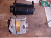
I initially ordered a 6 volt
alternator from Chevs of the 40s along with the universal mounting
bracket kit (I recommend that you do not buy this kit, little did I know at the time that there
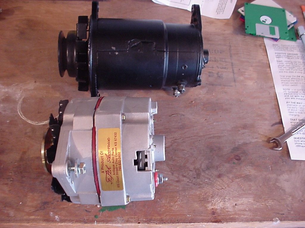
was a better solution available). The alternator is made by Fifth
Avenue from a company in Kansas. This delivers a regulated 7.5 volts @
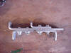
60 Amps. I removed the old generator and started assembling the quote "universal
alternator mounting bracket" that I got from Chevs of the 40s. See
photos 3 and 4. After having problems making it all align with the fan
belt I discovered a better alternator mount that is sold both by
Chevs of the 40's
and by
Patrick's
Antique Cars and Trucks (see Resource page). So, I swapped mounts
(photos 5 and 6) and the new one worked like a charm.
Wiring Steps for the
new Alternator:
(All of the pictures
below are expandable showing more detail. Be sure to allow enough time
for them to load. Then, move your mouse over the picture, click the arrow
box on the lower right part of the picture to enlarge it).
-
Print out photos 11
and 12 below.
-
Picture 11 is how
the original generator is wired from the factory. This is good for
reference.
-
Remove the generator
and keep all the wires in place in the car to connect up to the Alternator
as you will need the heavy Dark Brown wire. Install the Alternator.
-
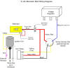
Refer to picture 12.
When your ready to wire the Alternator, remove the 2 heavy Red wires that
are connected to terminal 1 on the voltage regulator.
-
Remove the heavy
Dark Brown wire from terminal 2 of the voltage regulator.
-
Insert the plastic plug that
came with the Alternator into the socket on the Alternator. This plug has a
short Red and a long Yellow wire connected to it. See picture 9.
-
Connect the far end
(the end that use to connect to the generator) of the heavy Dark Brown wire
to the Alternators Red terminal (screw). Also....
-
Also connect the
short Red wire that comes from the Alternator plug to this screw on the
Alternator. Secure the nut.
-
Connect the 2 heavy
Red wires and the other end of the heavy Dark Brown wire (from steps 4 and 5
above) together. I bolted them together with a fairly heavy screw (#10
will work) and
nut. Then, I taped the nut and screw with black electrical tape to prevent it
from shorting anything. See picture 10 below.
-
Route the long
Yellow wire from the Alternator plug up along next to the heavy Dark Brown
wire where it runs along the wheel well. This Yellow wire end needs to
connect to the + terminal of the Ignition Coil. I continued to route
the yellow wire along the back firewall, in back of the engine, and down to
the Ignition coil. You can see the Yellow wire in pictures 8,9, and 10.
Use wire ties to secure this. The + terminal of the coil should also have a
Pink wire connected to it.
-
Congratulations your
done.
-
The voltage
regulator is no longer needed. I left the Blue wire still connected
even though it does not do anything now in the new configuration.
-
You do not have to
do anything else. When you start the car, even the Ammeter will work
correctly showing a + charge as you step on the gas.
-
When you start the
car, be sure to double check and make sure the fan belt rides well etc.
|
|
|
|
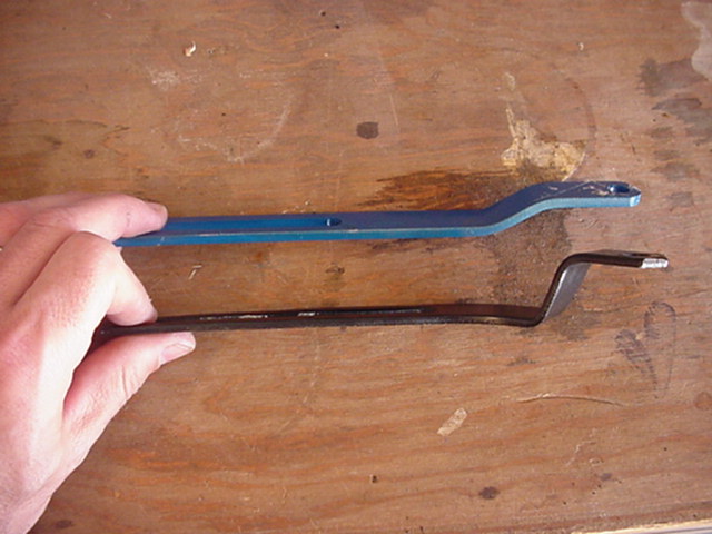
1. The old generator and alternator
Black generator and new 7.5 volt alternator comparison picture. |
|
|
|
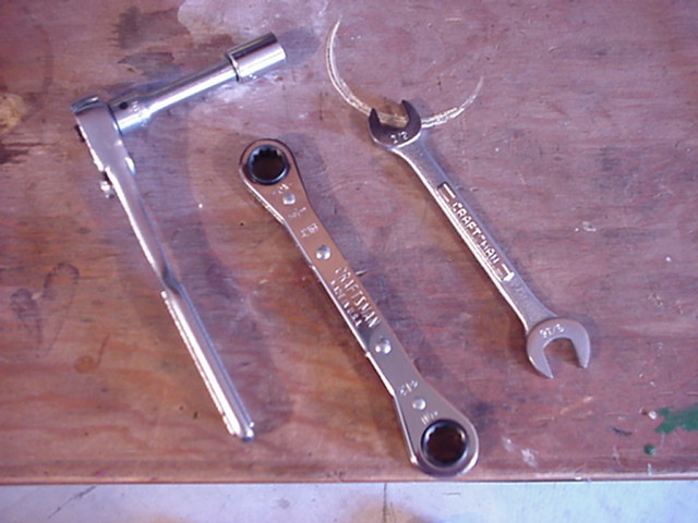
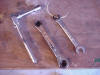
2. Typical Tools Needed
Ratchet and open end wrentches. |
|
|
|
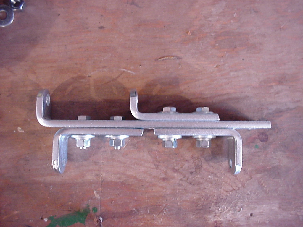
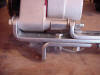
3. Universal Alternator Bracket
Assembled alternator bracket. What a mess this is. Don't buy it! |
|
|
|
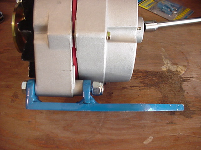
4. Attached to Alternator
See the slopply way this fits on to the alternator. |
|

|
|
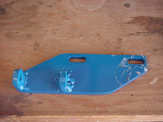
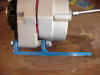
5. Buy This Mount
This is the baby you need. Call up Patrick's Antique Cars and Trucks or Chevs of the 40's to order one. See the Resource page to get the phone numbers. |
|
|
|
|
|
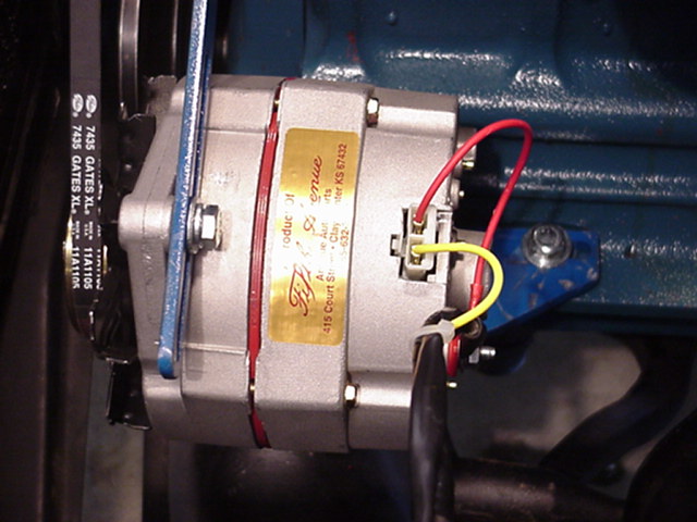
6. Mount and Alternator
Nice clean assembley. |
|

|
|
7. Support Arm
Patrick's also includes the exact new top mount arm for the alternator. Fits like a glove. The old stock arm typically will not work with alternator. |
|
|
|
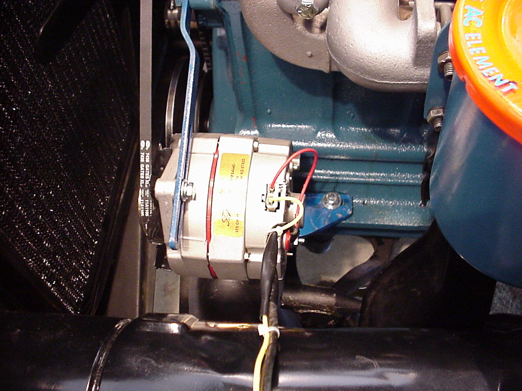
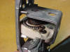
8. Installed and Wired
Everything lines up perfect. |
|

|
|
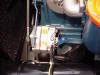
9. Close Up
You will also need a bit longer fan belt. I installed a Gates # 7435. |
|

|
|
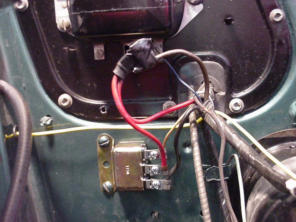
10. Close up of Mod
The 2 heavy red wires and the Dark Brown wire from the Alternator is bolted toghether under the wad of black tape. |
|
|
|

|
|
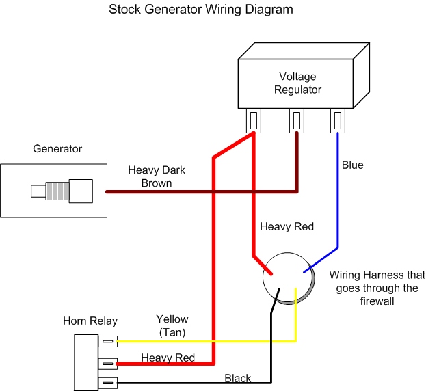
11. Wiring Diagram of Stock System
This is the configuration of the generator wiring system as made from the factory. Compare this to picture 12 and read text about how to make the wiring mods. |
|
|
|
12. Wiring of Alternator Configuration
Print out and follow the pictorial on how this mod is done. It is very simple to wire. |
|
|
Dashboard
Lights Don't Turn-on: Fixing Headlight Switch
If your dashboard
lights don't turn-on when you pull you headlight switch, and you are sure
all your bulbs are wiring is ok, chances are you have a bad light dimmer
control in the actual headlight switch. To verify this, you need to
remove the actual headlight switch from the car and do some continuity
testing or a close up visual inspection.
To remove the
headlight switch, first push the little button on the switch to release and
pull out the knob shaft. Then, unscrew the set screw and remove the
switch. Get some marking tape and label all the wires that connect to the
switch to make sure you get them on the correct switch terminals when you
are finished.
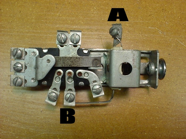
Referring to Figure
1 below, voltage is applied to the dimmer control through terminals A and B.
It is very common for the dimmer coil to be burned out. When this happens,
there is an open circuit and no voltage will be sent to the dashboard lights
via Terminal A. Instead of buying a new headlight switch, it is
possible, depending on where your open is on the coil, to repair the open
circuit.
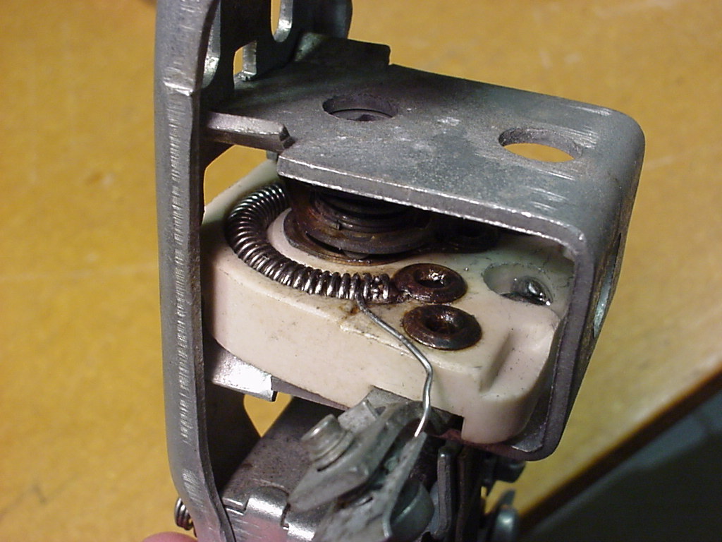
If you look close in
Figure 2, you can see where this coil opened up. The open coil is just a
coil turn to the right of where I inserted a wire in the coil unit itself.
To fix this, just insert a small piece of #22 or #20 AWG wire in-between two
good coils previous to the "open". This is shown in Figure 2.
Connect the other end of the wire to Terminal A.
This will shunt the
open and will make the dimmer control functional again. Note, that you
can't solder a wire to the nichrome coil, as the solder does not stick. So,
the friction of the wire stuck in-between the coils will hold up for normal
dimmer use. Thus, saving you having to buy a new hard to find,
headlight switch.
|
|
|
|
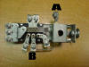
Figure 1
Headlight switch. Terminals A & B are the connections for the dimmer control. |
|
|
|
Figure 2
Fixed up with a wire inserted in the dimmer coil to bypass the open circuit. |
|
|
|